
辽宁虎驰科技传媒有限公司创立于1999年,专注于为商业零售连锁企业提供营销服务全面解决方案。
虎驰拥有16年的传统印刷服务经验,秉承“以变领未来”的理念,专注整合营销和深度推广。在保证传统的商务印刷领域优势的基础上,虎驰不断求变、 创新,由原始的传统印刷企业转型为包含营销策划、设计印刷、科技应用的多维跨界营销服务集合体,形成了 “商务印刷”、“全案策划”与“互联网营销及数字科技应用”于一体的整合营销服务体系,具备了差异化的体系竞争力...
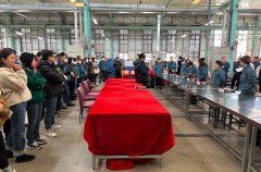
2023虎驰抽页技能大赛

2023年3月4日引进全新试卷胶订联动线
虎驰科技传媒 智者当量力而行,匠人当守正创新 https://v.douyin.com/MX8BuEA/ (来抖音,看视频)

2022第二届虎驰杯秋季趣味运动会圆满落幕 沐浴金秋的阳光,走进欢乐的海洋。带着青春的豪迈,挑战激烈的赛场。在这收获希望和喜悦的季…


